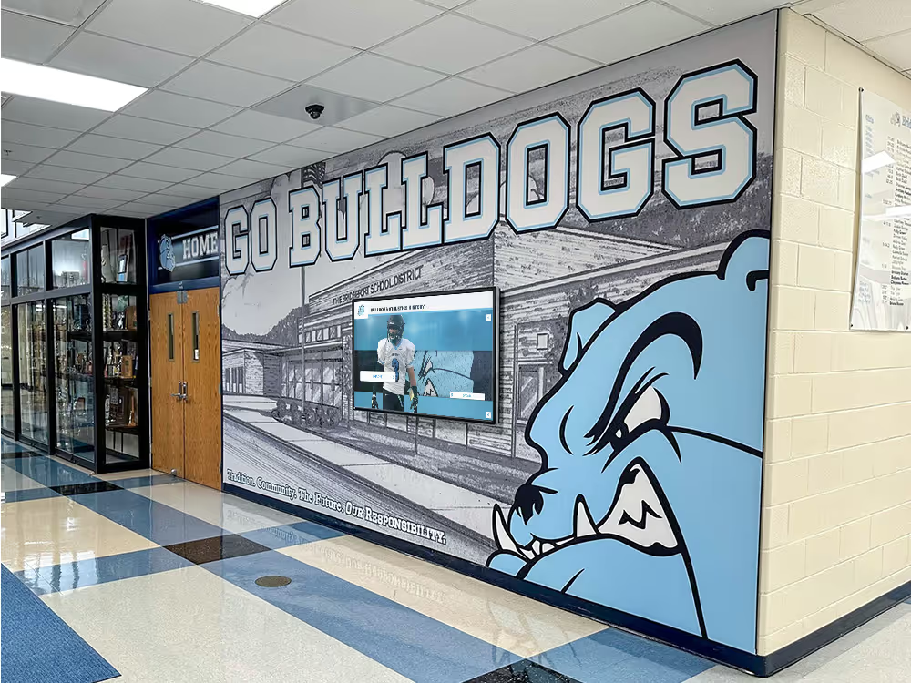
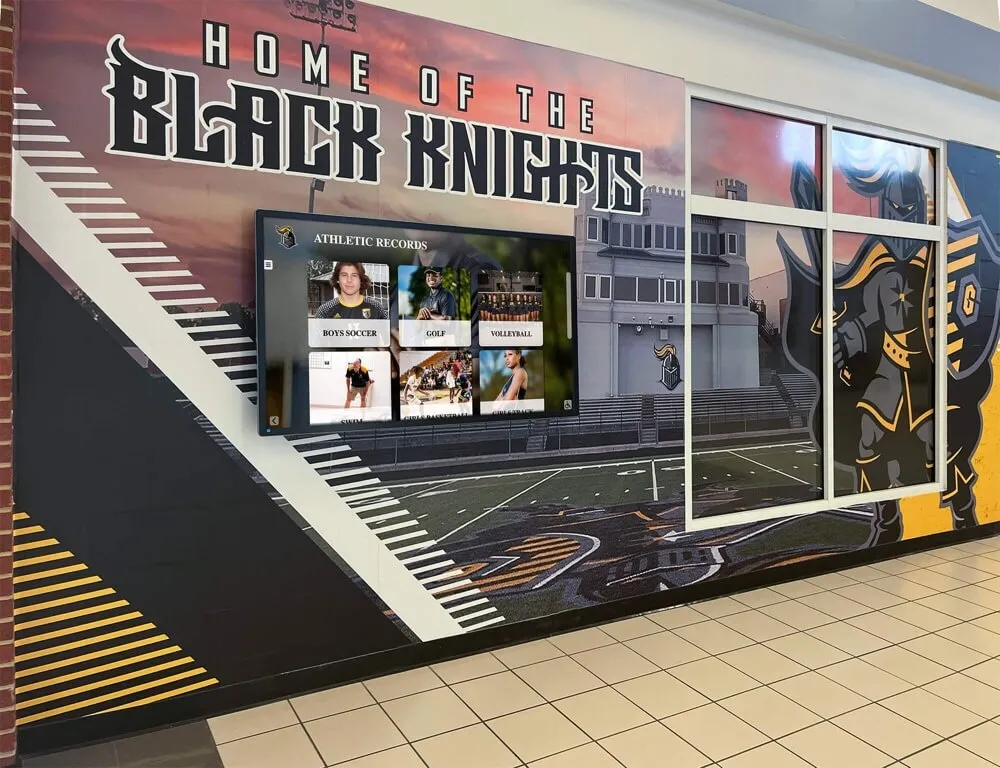
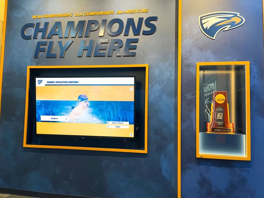
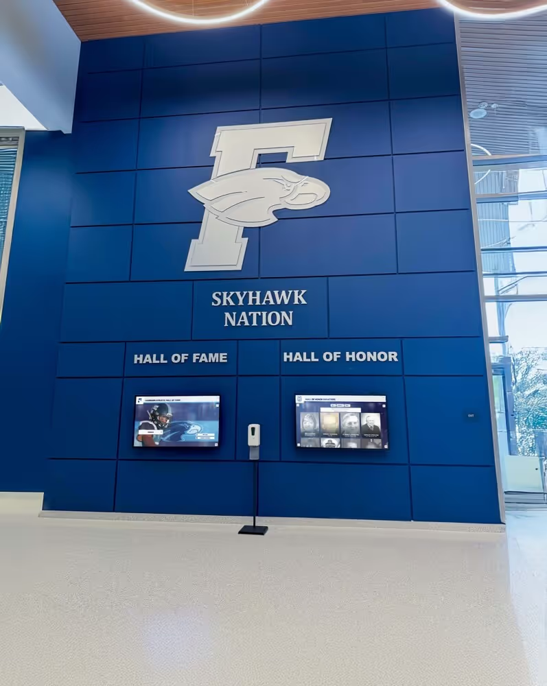
A school’s touchscreen recognition display can survive years of daily public interaction—fingerprints, casual bumps, humidity swings—and then fail silently because a technician grabbed the wrong edge of the controller board while swapping a USB cable. Electrostatic discharge is invisible, fast, and cumulative: a single discharge event may not destroy a component outright but can weaken it enough to cause intermittent failures weeks later during a championship ceremony or alumni induction event. In carpeted school hallways where students shuffle past lobby kiosks all day, static voltage buildup is a persistent and underestimated threat.
ESD damage to recognition display electronics is almost entirely preventable. The controls are neither expensive nor complicated, but they require consistency: a wrist strap that goes on every time, a grounded workbench that gets verified before every service call, and a site assessment that happens before the display enclosure is opened for the first time. Without a written checklist that captures those controls, the procedures exist only in one technician’s memory—and are skipped whenever that person is unavailable.
This recognition display electrostatic discharge protection checklist gives school IT coordinators, facilities leads, and AV technicians a structured, phase-by-phase set of controls covering site assessment, installation, ongoing maintenance, and personnel training. Every item is actionable and can be assigned to a named team member before the first panel is uncrated.
Nothing in this article constitutes legal or safety advice. Schools should follow manufacturer guidance, district facilities policies, and applicable electrical codes when modifying grounding infrastructure or installing display hardware.
The short answer: effective ESD protection for a school recognition display requires three coordinated layers—a properly grounded installation environment, personnel equipped and trained to handle sensitive electronics, and documented procedures that are followed every time the enclosure is opened. The full checklist below provides the master control table, a site-assessment walkthrough, step-by-step installation controls, ongoing maintenance requirements, and a personnel training record format your team can adapt this semester.
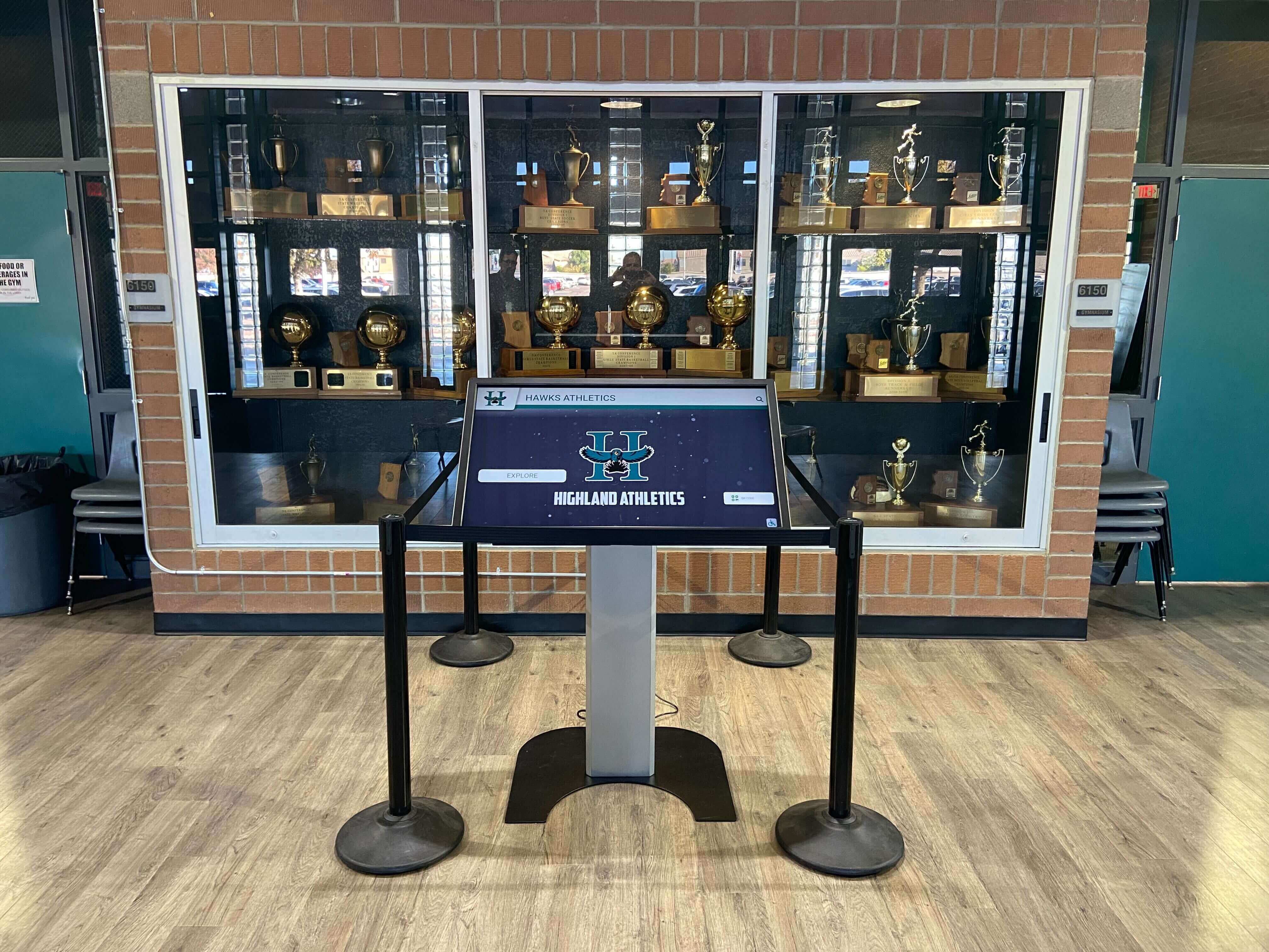
ESD Protection Master Checklist
Use this table as your working document. Assign each item to a responsible team member before uncrating any display hardware. Store the completed checklist in the display’s installation file alongside your cable map, network runbook, and power quality log.
| Checklist Item | Phase | Owner | Status | Review Trigger |
|---|---|---|---|---|
| Survey flooring material at each display location | Site Assessment | Facilities Director | ☐ Pending | Before installation planning |
| Measure ambient relative humidity at each location | Site Assessment | IT Coordinator | ☐ Pending | Before installation and each semester |
| Document HVAC airflow direction relative to display positions | Site Assessment | Facilities Director | ☐ Pending | Before installation planning |
| Identify nearest dedicated ground point for each display location | Site Assessment | Electrician | ☐ Pending | Before installation |
| Test continuity of building electrical ground at each outlet | Site Assessment | Electrician | ☐ Pending | Before installation |
| Verify display enclosure will be bonded to building ground | Site Assessment | Electrician | ☐ Pending | Before installation |
| Install anti-static floor mats at each maintenance access point | Installation Prep | Facilities Director | ☐ Pending | Before first service call |
| Verify anti-static mat ground cord is connected and continuity-tested | Installation Prep | IT Coordinator | ☐ Pending | Before each service session |
| Confirm personnel wrist straps are available for every technician who will handle internal components | Installation Prep | IT Coordinator | ☐ Pending | Before each service session |
| Verify wrist strap continuity with wrist strap tester before each use | Installation Prep | AV Technician | ☐ Pending | Before each service session |
| Bond wrist strap ground cord to the same ground point as the anti-static mat | Installation Prep | AV Technician | ☐ Pending | Before opening any enclosure |
| Remove synthetic clothing (polyester, fleece) or cover with ESD lab coat before handling components | Personnel Controls | AV Technician | ☐ Pending | Before each service session |
| Discharge personal static by touching grounded metal before approaching the display | Personnel Controls | AV Technician | ☐ Pending | Each time before approaching open enclosure |
| Transport display controller boards and touchscreen overlays in anti-static bags | Component Handling | AV Technician | ☐ Pending | Any time components are removed from enclosure |
| Place components on anti-static mat surface, not on cardboard or bare table | Component Handling | AV Technician | ☐ Pending | During every service session |
| Handle PCBs by edges only — do not touch solder pads, connectors, or ICs with bare hands | Component Handling | AV Technician | ☐ Pending | During every service session |
| Keep all replaceable components in sealed anti-static packaging until the moment of installation | Component Handling | AV Technician | ☐ Pending | During component replacement |
| Verify display enclosure metal frame is bonded to earth ground via green or green-yellow wire | Installation | Electrician | ☐ Pending | During installation and after any enclosure modification |
| Confirm display power supply ground pin is connected and continuity-verified | Installation | Electrician | ☐ Pending | During installation |
| Document ground continuity measurement (ohms) in the display installation record | Installation | Electrician | ☐ Pending | At commissioning and annually |
| Confirm the touchscreen controller USB cable is routed away from high-voltage supply lines inside the enclosure | Installation | AV Technician | ☐ Pending | During installation |
| Apply conductive gaskets or bonding tape where enclosure panels meet, if required by manufacturer | Installation | AV Technician | ☐ Pending | During installation |
| Label the anti-static mat ground cord connection point with a permanent tag visible during service | Installation | IT Coordinator | ☐ Pending | At installation |
| Verify relative humidity at display location is above 40% RH — add humidification if consistently below | Environmental | Facilities Director | ☐ Pending | Each semester and after HVAC changes |
| Confirm HVAC air supply diffusers are not directed at open enclosure panels during maintenance | Environmental | Facilities Director | ☐ Pending | Before each service session |
| Post ESD precaution notice inside every display enclosure access panel | Training & Documentation | IT Coordinator | ☐ Pending | At installation |
| Train all technicians who service the display on wrist strap use, anti-static mat setup, and component handling | Training & Documentation | IT Coordinator | ☐ Pending | Before first service call and annually |
| Record technician ESD training completion dates in the display maintenance log | Training & Documentation | IT Coordinator | ☐ Pending | After each training session |
| After any component replacement, power cycle the display and verify full functionality before closing the enclosure | Validation | AV Technician | ☐ Pending | After every component service event |
| Confirm touch calibration is accurate at all four screen corners after any internal service | Validation | AV Technician | ☐ Pending | After every component service event |
| Inspect anti-static mat and wrist strap for wear or damage at the start of each semester | Maintenance | IT Coordinator | ☐ Pending | Each semester |
| Re-test ground continuity of enclosure frame annually | Maintenance | Electrician | ☐ Pending | Annually |
| Review ESD incident log for any anomalous component failures or unexplained display behavior | Maintenance | IT Coordinator | ☐ Pending | Quarterly |
Why School Recognition Displays Face Elevated ESD Risk
Electrostatic discharge occurs when two objects with different electrical charges come into contact and equalize. The discharge can reach thousands of volts in a fraction of a millisecond. Modern display controller boards, touchscreen overlays, and power supply components use CMOS and other semiconductor technologies that are sensitive to discharge events well below the threshold a person can feel—the human perception threshold for ESD is approximately 3,500 volts, while many display components can sustain latent damage from discharges as low as 100 volts.
School environments create several conditions that make ESD more likely and more consequential than typical commercial settings:
Carpeted hallways and lobbies. Carpet is one of the most effective static generators in a building. A student walking across a nylon carpet can accumulate 35,000 volts of static charge under low-humidity conditions. A lobby display kiosk positioned near the end of a carpeted corridor receives repeated proximity charges from hundreds of students each day, gradually building charge on any insufficiently grounded surface.
Low winter humidity. Most schools in northern climates experience indoor relative humidity below 30% during heating season. At 10–20% RH, static generation increases dramatically and discharge events become more frequent and more intense. A display that operates without incident in September may begin experiencing intermittent failures by February as heating season depresses interior humidity.
High technician turnover. School IT and AV teams often include part-time staff, district-shared technicians, or vendor service representatives who are not familiar with the school’s specific ESD controls. Without posted procedures inside the enclosure and a written checklist, ESD protection is practiced inconsistently.
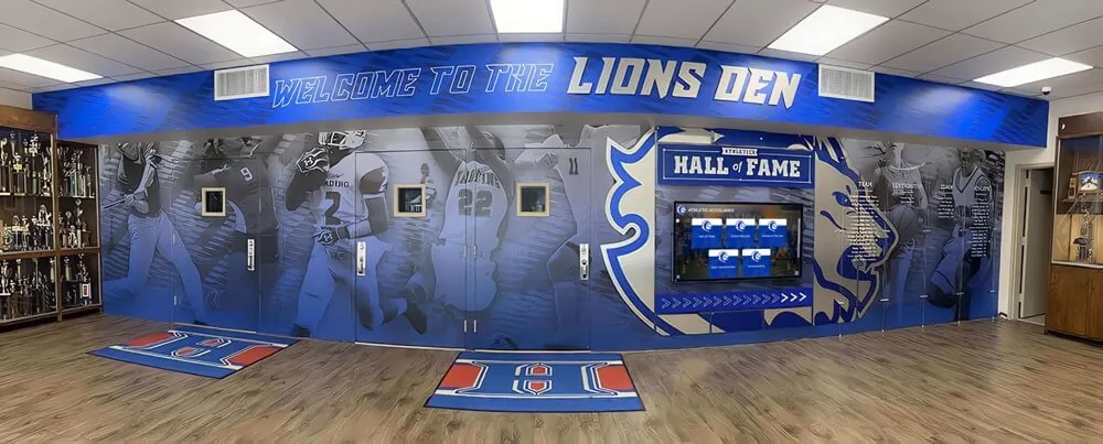
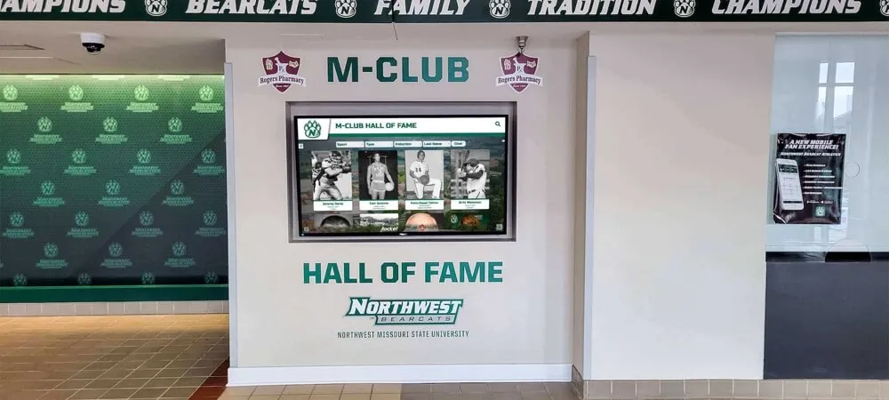
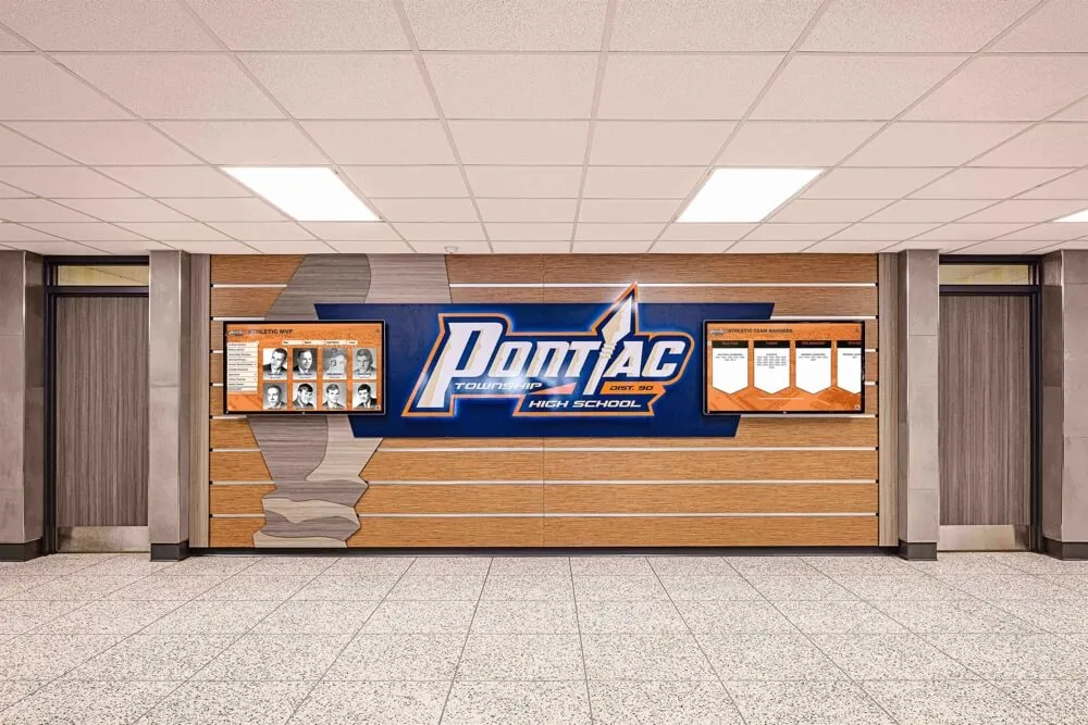
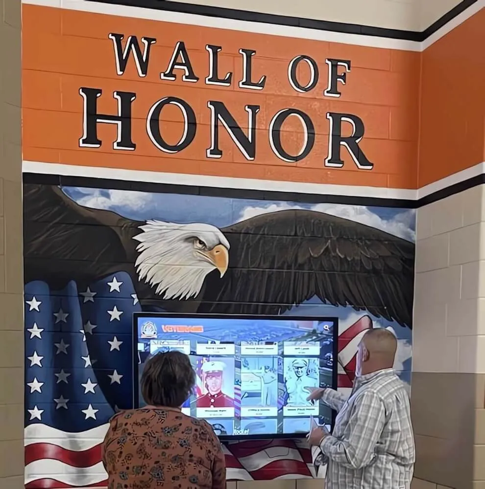
Public-facing mounting locations. Recognition displays for athletic hall of fame programs and donor recognition walls are mounted in high-traffic areas—lobby entrances, corridor intersections, and trophy alcoves—where visitors touch and approach the display surface constantly. This ongoing contact contributes to static charge accumulation on the display’s external surfaces, which can transfer to internal components during service.
Long service intervals. Unlike IT workstations that are accessed frequently, a recognition display may go six months or more between service visits. A technician who services the display infrequently is less likely to have ESD equipment immediately at hand and more likely to treat the service call as a simple cable swap rather than a sensitive electronics task.
Understanding these risk factors before installation is the foundation of a prevention strategy that protects the display’s electronics over its full service life.
Phase 1: Site Assessment
A site assessment conducted before installation identifies ESD risks that are easier and less expensive to address before the display is mounted than after.
Step 1.1 — Flooring Survey
Walk each planned display location and document the flooring material:
- Carpet: Any carpet type presents the highest ESD risk. Wool carpet generates less static than synthetic nylon, but both require anti-static mats at maintenance access points and may warrant permanent ESD-dissipative floor treatment for high-traffic installations.
- Vinyl composite tile (VCT): Standard VCT is not inherently anti-static. ESD-dissipative VCT is available and can be specified during renovation projects that involve recognition display corridors.
- Polished concrete: Typically lower ESD risk than carpet or standard tile, especially when unsealed. However, dry concrete in low-humidity conditions still generates static.
- Hardwood or engineered wood: Moderate ESD risk. Static generation increases significantly when coated with polyurethane finish.
Record the flooring material, approximate area affected, and nearest maintenance access path for each display location.
Step 1.2 — Humidity Assessment
Measure relative humidity at each display location during the school day using a calibrated hygrometer. Record the reading and note the season and HVAC operating state. If measurements fall below 40% RH:
- Identify whether building HVAC includes humidification capacity and whether it is operational.
- Consult with facilities management about adding spot humidification near display locations during heating season.
- Document the humidity baseline in the display installation record so future readings can be compared against it.
The 40% RH threshold is a practical industry reference point: below this level, static generation increases substantially and ESD events become more frequent. Schools managing athletic memorabilia and display archives alongside digital displays often track humidity for preservation reasons as well — these measurements serve double duty.
Step 1.3 — Grounding Infrastructure Assessment
Have a licensed electrician verify the following at each display location before installation:
- Confirm the outlet serving the display has a functional earth ground connection. Measure continuity between the ground pin and a verified earth ground reference.
- Identify the nearest grounding electrode or building ground bus that can serve as a bonding point for the display enclosure and anti-static mat.
- Document the ground conductor size and type available at each location.
- Note any locations where the electrical ground connection is absent, reversed, or floating — these require correction before display installation.
A display enclosure that cannot be bonded to a verified earth ground cannot be adequately protected against ESD. Correct grounding deficiencies at the electrical level first; anti-static mats and wrist straps supplement a proper ground but cannot substitute for one.
Phase 2: Installation Controls
ESD damage most commonly occurs during installation, not during daily operation. The internal electronics of a recognition display are exposed during uncrating, mounting, cable routing, and first-power-on — all moments when proper controls must be in place.
Step 2.1 — Anti-Static Mat Setup
Before opening any display enclosure:
- Position an anti-static mat on a stable surface at the maintenance access point. The mat should be large enough for a technician to stand on while reaching into the enclosure.
- Connect the mat’s ground cord to a verified earth ground point — the building ground bus, a grounded metal conduit, or the equipment ground wire in a nearby outlet. Do not use the neutral conductor as a ground reference.
- Test mat-to-ground continuity with a resistance meter. A functional anti-static mat should measure between 1 megohm and 1 gigohm to ground. Values outside this range indicate a damaged mat or a failed ground connection.
- Record the test result and the ground connection point in the service log.
Step 2.2 — Wrist Strap Verification
Every technician who will handle internal components must:
- Put on an ESD wrist strap before approaching the open enclosure.
- Connect the wrist strap ground cord to the same ground point as the anti-static mat.
- Test the wrist strap with a dedicated wrist strap tester before beginning work. A functional strap measures in the range of 1 megohm to the ground point. A failed wrist strap — broken cord, broken carbon-embedded wrist band — measures out of range and must be replaced before continuing.
- Keep the wrist strap on continuously while any enclosure panel is open.
Wrist strap testing takes approximately ten seconds. Teams that skip this step most often do so because no tester is available on-site. Include a wrist strap tester in every display installation kit and in every service kit carried to recognition display service calls.
Step 2.3 — Enclosure Bonding
Once the display is physically mounted:
- Attach a green ground wire from the display enclosure’s designated bonding lug to the building ground bus or the equipment ground wire in the supply circuit. If the manufacturer does not provide a bonding lug, consult the installation manual for the approved bonding method.
- Measure continuity between the enclosure metal frame and the building ground reference. Record the measurement in ohms.
- Confirm the power supply chassis ground connection is secure and that the green (or green-yellow) ground wire from the power inlet is firmly terminated.
- Document all ground connections in a wiring diagram stored in the display installation file.
Schools installing donor recognition walls with multiple display panels in a single installation should treat each panel enclosure as a separate bonding point — chain bonding from panel to panel is not an adequate substitute for independent connections to the building ground.
Phase 3: Component Handling Controls
Recognition display service calls frequently involve replacing or reseating internal components: USB touchscreen controllers, HDMI signal boards, power supply boards, or memory modules in the display’s embedded computing platform. Each of these components must be handled using the same controls applied during initial installation.
Step 3.1 — Anti-Static Packaging
All components traveling to and from a service site must be transported in properly rated packaging:
- Anti-static bags (pink/clear): Dissipate static from the surface of the bag but do not shield from external fields. Acceptable for short-distance transport of components that are not extremely field-sensitive.
- Shielded bags (metallic, silver-gray): Provide both surface dissipation and Faraday-cage shielding. Required for field-sensitive components such as PCBs with exposed CMOS devices, RAM modules, and solid-state storage.
- Anti-static foam: Use when placing components in rigid cases. Do not use standard polyurethane (white or yellow) foam — it is highly triboelectric and will charge components stored in contact with it.
Label the exterior of all anti-static packaging with the component name, display identifier, and date of removal. Keep components in sealed packaging until the moment of installation on the grounded anti-static mat.
Step 3.2 — Handling Technique
When removing or installing internal components:
- Touch the grounded display enclosure chassis before picking up any component to equalize charge.
- Hold PCBs by the edges only. Avoid touching solder pads, exposed component leads, edge connectors, and IC packages.
- Do not slide components across any surface that is not a verified anti-static mat. Cardboard, bare workbench surfaces, and fabric are all static generators.
- Place components face-up on the anti-static mat surface while connecting cables or preparing mounting hardware.
- Minimize the time components spend outside sealed packaging or outside the grounded enclosure.
Phase 4: Environmental and Ongoing Controls
ESD protection is not a one-time installation task. The risk environment changes with seasons, HVAC adjustments, and facility modifications. Ongoing controls ensure protection remains effective across the display’s full service life.
Step 4.1 — Seasonal Humidity Monitoring
Measure and record relative humidity at each display location at the start of each semester:
- Fall semester start (August–September): Baseline before heating season begins.
- Spring semester start (January–February): Peak ESD risk period in most climates. Compare against fall baseline.
If readings consistently fall below 40% RH during heating season, document the finding for the facilities director and escalate to the district’s energy and environmental team. Spot humidifiers placed in display alcoves can raise local humidity without requiring building-wide HVAC modifications.
Step 4.2 — Anti-Static Mat and Wrist Strap Inspection
At the start of each semester:
- Visually inspect every anti-static mat for cuts, contamination, or connection hardware damage. A mat with a severed ground cord connection is a non-grounded rubber mat — it provides no protection.
- Test mat continuity to ground and record the measurement.
- Inspect every wrist strap in the service kit for worn or cracked bands and damaged coiled cords.
- Replace any mat or strap that fails the visual inspection or continuity test. Anti-static mats typically have a service life of three to five years under normal use; wrist straps and ground cords should be replaced annually or after any visible damage.
Step 4.3 — Ground Continuity Verification
Have a licensed electrician re-test the enclosure-to-building-ground continuity measurement annually as part of the display’s preventive maintenance inspection. Compare the measurement against the commissioning value recorded in the installation file. An increase in resistance may indicate:
- A loosened bonding connection inside the enclosure
- Corrosion on the ground wire termination
- A change in the building’s grounding infrastructure during a renovation
Schools that manage interactive recognition archives and display systems across multiple buildings should schedule these inspections building-by-building on a rolling annual calendar rather than trying to test all displays at the same time.
Phase 5: Personnel Training and Documentation
The most common ESD failure mode in school recognition display deployments is not a gap in equipment — it is a gap in procedure. A wrist strap that sits in the bottom of a tool bag untested, a new technician who was never shown how to use an anti-static mat, or a vendor service representative who opens the enclosure without asking about ESD controls: these are the scenarios that produce latent damage.
Step 5.1 — Enclosure Notice Labels
Post a permanent ESD precaution notice on the inside of every access panel. The notice should include:
- Required PPE: wrist strap, ESD lab coat (if available)
- Required equipment: anti-static mat, ground cord
- Ground connection point location for this specific installation
- Contact information for the IT Coordinator responsible for this display
This notice functions as a just-in-time training document for any technician — internal staff or vendor representative — who opens the enclosure. Schools whose recognition programs span multiple buildings benefit significantly from these labels, because a technician who primarily services one building may be unfamiliar with the specific ground point configuration in another.
Step 5.2 — Training Record
Maintain a training log in the display’s installation file. For each technician authorized to service the display internally, record:
| Technician Name | Role | Training Date | Trainer | ESD Topics Covered | Expiration |
|---|---|---|---|---|---|
| (name) | IT Coordinator | (date) | (trainer) | Wrist strap use, mat setup, component handling, ground verification | (annual renewal) |
| (name) | AV Technician | (date) | (trainer) | Wrist strap use, mat setup, component handling | (annual renewal) |
| (name) | Vendor Representative | (date) | (trainer) | Site-specific ground point, required PPE, escalation contacts | (per visit) |
Require vendor representatives to complete a brief site-specific orientation — five minutes, covering the ground point location, required PPE, and the contact to call before opening the enclosure — before beginning any service visit. Document this orientation in the log.
Step 5.3 — Incident Log
Maintain an ESD incident log alongside the display’s maintenance records. Record any event that may have involved an ESD exposure:
- Unexplained component failures or intermittent behavior following a service visit
- A service visit where documented ESD controls were not fully followed
- A visible arc or spark observed during service
Schools managing sportsmanship award programs and athletic recognition displays across multiple facilities should treat anomalous component failures as potential ESD events until confirmed otherwise — early documentation supports warranty claims and informs future prevention priorities.
ESD Risk and Control Quick-Reference Table
| Risk Scenario | ESD Risk Level | Required Control | Review Frequency |
|---|---|---|---|
| Carpeted lobby display location | High | Anti-static mat, grounded enclosure, wrist strap required for all internal service | Before each service session |
| Low humidity (below 40% RH) during heating season | High | Humidity monitoring and documentation; spot humidification if below 30% RH | Each semester |
| Vendor representative service visit | High | Site orientation, wrist strap and mat required, training log entry | Each vendor visit |
| Component replacement (PCB, touchscreen overlay) | High | Anti-static bag transport, anti-static mat handling, wrist strap, edge-only contact | During each service event |
| Cable reseating (HDMI, USB, power) with enclosure open | Moderate | Wrist strap required; discharge to chassis before touching internal cables | During each service event |
| Display firmware update (no enclosure opening) | Low | Standard IT controls; no special ESD equipment required | As scheduled |
| Polished concrete floor location | Moderate | Anti-static mat during service; humidity monitoring | Before each service session |
| Outdoor-rated or vestibule display (temperature extremes) | High | Additional humidity monitoring; verify gasket integrity seasonally | Each semester |
People Also Ask
What is electrostatic discharge and why does it damage recognition display electronics?
Electrostatic discharge (ESD) is the rapid transfer of electrical charge between two objects with different charge levels when they contact or come close to each other. The discharge can produce voltage spikes of thousands of volts in nanoseconds. Modern recognition display electronics—touchscreen controllers, embedded computing platforms, and signal processing boards—use CMOS and MOSFET transistors that can sustain permanent damage or latent weakening from discharges as low as 100 to 200 volts, well below the 3,500-volt threshold a person can feel. Damage may not appear immediately; a weakened component may operate normally for weeks before failing unexpectedly, making the cause difficult to trace.
How do I know if my school’s recognition display location has an ESD risk?
The primary indicators are flooring material and relative humidity. Any display location with carpeted flooring presents an elevated ESD risk, particularly during heating season when indoor humidity falls below 40% RH. You can measure relative humidity with an inexpensive digital hygrometer. If the display is in a carpeted hallway or lobby and your school runs heating from November through March, assume ESD risk is elevated during those months and apply the full set of controls in this checklist before any service visit.
What equipment do I need to protect a school recognition display from ESD during service?
The core equipment set for a single technician servicing a recognition display is: a wrist strap with a ground cord and 1 megohm resistor, a wrist strap tester, an anti-static mat with its own ground cord, and anti-static (shielded) bags for any components removed from the enclosure. The total cost of this equipment is typically under $100 and should be included in every school IT or AV service kit used for display maintenance. Schools honoring youth athletes of the year and other recognition programs through touchscreen displays should budget for this equipment as part of the display’s ongoing maintenance cost.
Does the type of floor at a school affect ESD risk for touchscreen displays?
Yes, significantly. Carpet—especially synthetic nylon carpet common in school hallways—is the highest-risk flooring material, generating tens of thousands of volts of static under low-humidity conditions. Vinyl composite tile and polished concrete present lower but non-zero risk. Schools that are renovating display corridors can specify ESD-dissipative flooring products designed for environments with sensitive electronics. These products use carbon-loaded or conductive layers to bleed static to ground continuously, preventing charge accumulation near display locations.
How often should school IT teams re-test the ground connection on a recognition display enclosure?
Ground continuity should be verified at commissioning, after any modification to the enclosure or mounting, and annually as part of preventive maintenance. The measurement should be recorded in the display’s installation file each time and compared against the previous value. An increasing resistance measurement — even if still within acceptable limits — is a leading indicator of a deteriorating connection that should be investigated before it fails. Schools managing multiple displays across a campus can schedule ground tests on a building-by-building rolling calendar to avoid testing all displays simultaneously.
What is latent ESD damage and how does it affect recognition displays?
Latent ESD damage is the weakening of a semiconductor device from a discharge event that is insufficient to cause immediate failure. The device continues to function after the event but operates with reduced reliability — it may fail under normal load, elevated temperature, or sustained operation days or weeks later. Latent damage is the most dangerous form of ESD damage for recognition displays because it produces failures with no apparent connection to a service event, making diagnosis difficult. The only reliable defense against latent damage is preventing the discharge in the first place through consistent application of grounding, wrist strap, and component handling controls.
Connecting ESD Controls to Long-Term Display Reliability
Every failed component on a public-facing recognition display has an audience: the students, alumni, and visitors who walk past a dark screen, see a garbled layout, or find the interactive athletic record board unresponsive before a banquet. For schools that have invested in digital donor recognition programs or interactive athletic history archives, component failure at a high-visibility moment is a significant reputational event, not just a maintenance ticket.
ESD controls eliminate an entirely preventable category of component failure. The checklist in this article does not require new infrastructure for most schools — a properly wired outlet already provides the ground reference, and the anti-static mat connects to it. The personnel controls take ten seconds to implement at the start of each service session. What they require is consistency: the same wrist strap tested before every service call, the same mat deployed every time a panel is opened, the same training completed by every technician added to the service rotation.
Schools with multiple display installations — lobby kiosks, hallway honor walls, trophy alcove screens — should treat this checklist as a template and complete a separate instance for each display location. Ground connection points, flooring types, and humidity profiles differ from one corridor to the next. A checklist that is accurate for the main lobby may not reflect the conditions in the gymnasium hallway or the media center entrance.

Once your ESD controls are documented and in place, the checklist serves a second function: it is evidence. A documented ground continuity test, a wrist strap test result, and a signed technician training log provide the IT Coordinator with a defensible record of due diligence if a component fails and a warranty claim or vendor dispute follows. Schools that have formalized their digital recognition display programs with multi-year service contracts should incorporate ESD compliance requirements into those contracts — vendor technicians who cannot demonstrate familiarity with ESD controls should not be performing internal service on display electronics.
A completed recognition display electrostatic discharge protection checklist means your facilities and IT teams have a documented, repeatable set of controls that any technician can follow regardless of experience level. The five phases above — site assessment, installation controls, component handling, environmental monitoring, and personnel training — cover every ESD risk scenario that affects school recognition displays in real K–12 and higher education operating conditions. Apply the controls consistently and the display’s electronics will reach their full service life; skip them and you are absorbing a preventable failure risk every time someone opens the enclosure.
Want a recognition display platform that includes complete installation documentation before deployment?
Rocket Alumni Solutions deploys touchscreen hall of fame displays, donor recognition walls, and interactive athletic record boards for schools — with the grounding specifications, site requirements, and service documentation your IT and facilities teams need before installation day.